

Take a standard SMT reflow oven built for populating printed circuit boards and try running a heat pipe radiator module through it — a stack of copper heat pipes soldered flat onto a thick aluminum baseplate — and it usually won't work. Not because the oven is broken, but because it was built to solve a different problem. This piece covers why heat pipe-to-baseplate reflow soldering behaves so differently from PCB reflow, what that means for oven sizing and profile setup, and what a reliable process actually looks like for LED, street lighting, and other high-power heat pipe radiator assemblies.
Why a Standard SMT Reflow Oven Struggles With Heat Pipe Radiators
A standard SMT reflow oven is sized around PCBs and small surface-mount components — low thermal mass parts that heat up and cool down quickly, so the oven's heating zone doesn't need to be very long to bring them to temperature and hold them there. A typical PCB reflow heating zone runs around 2 meters.
A heat pipe radiator assembly is a different animal. A copper heat pipe module soldered to a 5mm aluminum baseplate carries far more thermal mass than a circuit board, and both the heat pipes and the baseplate have high thermal conductivity, which means they pull heat out of the surrounding air fast and resist warming up evenly. Run that assembly through a 2-meter heating zone built for PCBs and the temperature swings inside the oven chamber as the part passes through — the part never gets a stable, even soak, and joint quality suffers as a result. Matching this thermal mass typically calls for a heating zone on the order of twice the length used for standard PCB work, giving the assembly enough time in each zone to actually reach thermal equilibrium before moving to the next stage.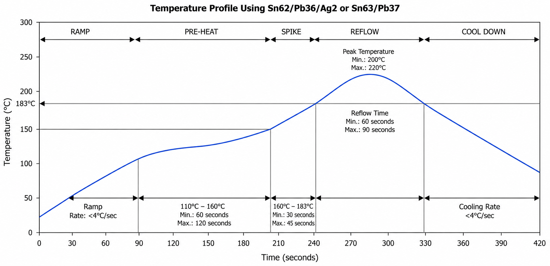
The Joint Itself Is a Different Shape
PCB reflow soldering joins small component leads to pads on the board surface — the solder joint sits on the outside edge of a small part, and there's not much thermal mass to move through the joint itself. A heat pipe-to-baseplate joint is closer to the opposite case: the heat pipe sits flat against the baseplate across a wide contact area, and the solder has to fill and wet that entire contact surface, not just a small lead. That's a much larger effective pad area carrying a much bigger thermal load, and it behaves more like joining two solid pieces of metal than like attaching a component to a board.
This distinction matters for process design because a profile tuned for small, quick-heating component joints doesn't reliably wet a large, thermally massive contact surface. Getting consistent wetting across the full heat pipe-to-baseplate contact area is the core process challenge, not an afterthought.
Setting Up the Reflow Profile Correctly
A heat pipe radiator reflow profile follows the same broad stages as any reflow process — preheat, soak, reflow, cooling — but each stage needs to be stretched and tuned for the thermal mass involved.
• Preheat — brings the assembly up gradually so solvents in the paste evaporate and the flux activates without thermal shock to the joint.
• Soak — holds the assembly at an intermediate temperature long enough for the heat pipes and the thick baseplate to reach a uniform temperature throughout — this stage typically needs to run longer than a standard PCB profile, precisely because of the thermal mass mismatch covered above.
• Reflow (peak) — for lead-free solder (SAC305, melting around 217°C), industry practice puts the peak temperature roughly 20–40°C above the alloy's melting point — typically in the 240–260°C range. A peak significantly above that range risks damaging the joint, degrading flux performance, or affecting nearby materials, and doesn't improve wetting once the solder is already fully liquid.
• Cooling — a controlled cooling rate, commonly in the range of 3–5°C per second, solidifies the joint while limiting the thermal stress that a fast, uneven cool-down can leave in a large-area solder joint.
Independent temperature control across each zone — often across 8 to 10 zones for this class of assembly — combined with adjustable conveyor speed, is what lets the profile be tuned to the specific baseplate thickness, heat pipe count, and fixture geometry in front of you, rather than running one fixed profile and hoping it fits.
Why Lead-Free and Nitrogen Atmosphere Matter Here
Lead-free solder is the standard for current production, both for regulatory reasons and because it's simply what most supply chains are set up for now. It also has a narrower process window than older tin-lead solder, which raises the stakes on getting the profile right — this is where a controlled, multi-zone oven earns its keep. For heat pipe and baseplate assemblies specifically, running the reflow stage under a nitrogen atmosphere reduces oxidation on the exposed copper and aluminum surfaces during the extended soak this process needs, which improves wetting across that large contact area rather than leaving oxidized patches that keep the solder from bonding properly.
Five Requirements for a Reliable Heat Pipe Solder Joint
• Adequate, controlled heat — enough thermal energy to fully melt the solder and form a proper intermetallic bond across the whole contact area, without overheating the surrounding materials or the joint itself.
• Good wetting — the molten solder needs to spread evenly across the full contact surface; patchy wetting leaves voids that raise thermal resistance right where you need heat transfer most.
• Clean, oxide-free surfaces going in — both the heat pipe contact surface and the baseplate need to be clean and dry before paste application, since surface contamination is one of the most common root causes of poor wetting.
• Correctly designed paste application — stencil design and paste volume need to match the actual contact geometry between the heat pipe and baseplate, not be borrowed from a standard PCB stencil pattern.
• Stable fixturing during the cycle — the heat pipe has to stay correctly positioned against the baseplate through preheat, soak, and reflow — any shift during the cycle shows up as an inconsistent or incomplete joint.
What This Achieves in a Finished Assembly
Done correctly, reflow-soldered heat pipe radiators are commonly specified to hold LED junction temperature below 80°C and keep the temperature difference between the LED's copper base and the radiator itself within about 5°C — figures that are realistic targets for high-power LED street lighting and similar fixtures when the joint is properly wetted across its full contact area. Compared to mechanical clamping with thermal grease, a soldered joint removes the interface resistance that grease and clamping pressure never fully eliminate, and it holds up better over years of thermal cycling in outdoor fixtures.
Where This Fits in Heat Pipe Radiator Production
Reflow soldering the heat pipe-to-baseplate joint is a downstream step — it happens after the heat pipes themselves are built and sealed, covered in our heat pipe production process guide, and it's a separate process from the fin-array soldering covered for standard heat sink and vapor chamber assemblies in our reflow oven documentation. What's different here is the scale of the baseplate and the size of the contact joint, which is why the oven's heating zone length and profile need to be sized specifically for it rather than assumed from a general-purpose reflow line.
Talk to Us About Your Heat Pipe Radiator Line
We build lead-free hot air reflow ovens configured with the extended heating zones, independent multi-zone control, and nitrogen atmosphere option this class of assembly needs, sized to your baseplate thickness, heat pipe count, and fixture layout. Send us your assembly drawings and target output, and we'll work through the oven sizing and profile setup with you.
FAQ
Can a standard PCB reflow oven solder heat pipes to an aluminum baseplate?
Not reliably. A standard PCB reflow oven's heating zone is sized for low-thermal-mass boards and components, typically around 2 meters. A heat pipe radiator's thick baseplate and high-conductivity heat pipes need a longer heating zone — often roughly double — to reach a stable, even temperature before reflow, which most standard SMT ovens aren't built to provide.
What peak temperature should a heat pipe-to-baseplate reflow profile use?
For lead-free solder (SAC305), industry practice is a peak roughly 20–40°C above the alloy's melting point of about 217°C, typically landing in the 240–260°C range. Peaks well beyond that don't improve wetting once the solder is fully liquid and risk damaging the joint or surrounding materials, so higher isn't better.
Why is nitrogen atmosphere recommended for this type of reflow soldering?
The extended soak time needed to bring a thick baseplate up to temperature gives exposed copper and aluminum surfaces more time to oxidize in open air. A nitrogen atmosphere limits that oxidation during the longer soak, which helps the solder wet the full contact area evenly instead of being blocked by oxidized patches.
How is heat pipe-to-baseplate soldering different from soldering fins to a heat sink?
Both are reflow processes, but a heat pipe-to-baseplate joint typically involves a larger, flatter contact area carrying more thermal mass than a fin joint, which pushes the profile toward a longer soak and a wider heating zone. Fin arrays on a heat sink base plate are a related but distinct application, covered separately in our reflow oven documentation.
What causes poor wetting in heat pipe radiator solder joints?
The most common causes are surface contamination or oxidation on the heat pipe or baseplate before paste application, an underpowered or too-short soak stage that doesn't bring the assembly to a uniform temperature, and stencil/paste volume that wasn't designed for the actual contact geometry.
Can the reflow oven be configured for our specific heat pipe radiator design?
Yes. Heating zone length, zone count, conveyor speed range, and nitrogen atmosphere are all sized to your baseplate thickness, heat pipe layout, and target throughput, and the profile is validated on your own assembly before production.
-
Written by
CoolingThermal Engineering TeamCoolingThermal is an automation equipment manufacturer based in Kunshan, China, specializing in heat pipe and vapor chamber production equipment since 2017. Our engineering team designs, builds, and commissions complete production lines covering forming, degassing, welding, testing, and assembly processes. The technical content on this blog is written by the same team that develops the equipment — based on real production experience, not secondary research.


