

Vacuum Brazing vs Friction Stir Welding: How Should You Choose for a Liquid Cold Plate?
The right cold-plate joining process is determined by internal geometry, alloy system, weld access, pressure and life requirements, flatness, production volume and inspection capability. Vacuum brazing is usually the stronger candidate when one thermal cycle must join internal fins, multilayer features or many hidden interfaces. FSW is usually the first process to evaluate for accessible aluminum cover-plate designs that require strong joints, controlled heat input and a repeatable automated cycle.
In server, energy-storage, EV, laser and power-module projects, the same cold-plate drawing is often quoted with both processes. Either process can produce a reliable part. Problems start when the structure was designed without considering the joining method: lack of root penetration, braze alloy entering a channel, cover collapse, an exit keyhole, excessive flatness error or an inspection plan that costs more than expected.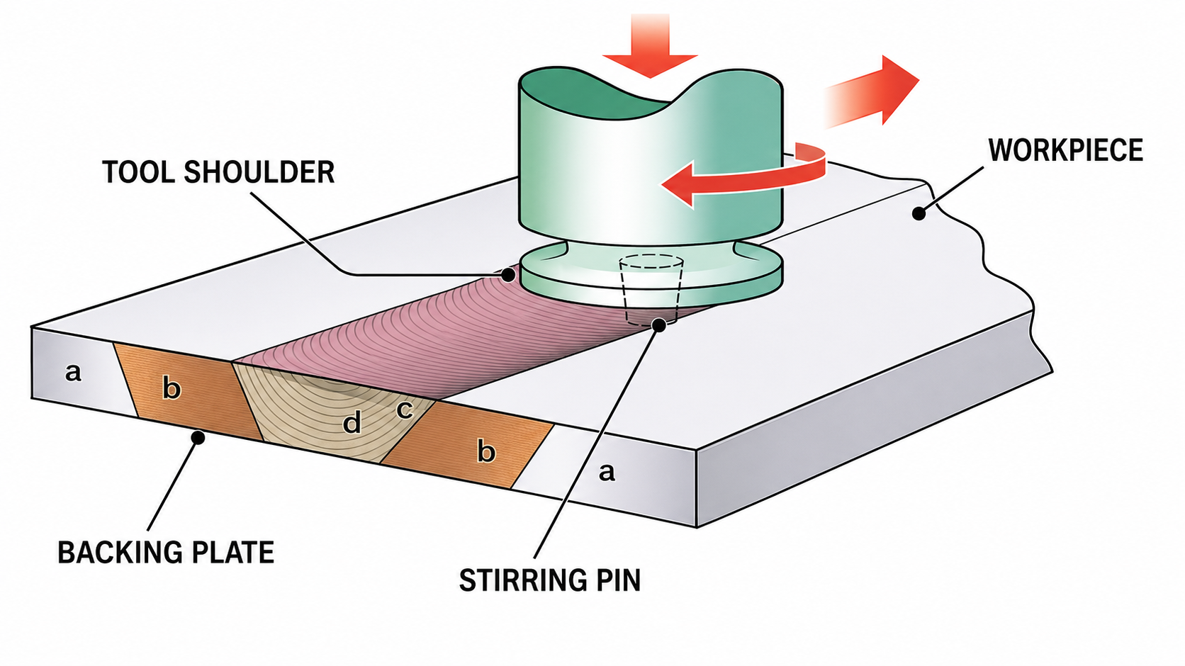
1. The Short Answer: Select by Structure and Validation Requirements
| Project condition | Evaluate vacuum brazing first | Evaluate FSW first |
| Internal structure | Multilayer construction, internal fins, turbulators, dense channels or many interfaces joined at once | Machined base plus cover, with a continuous and accessible weld path |
| Materials | Aluminum, copper and compatible filler systems; alloy brazeability must be checked | Most common for aluminum cold plates; other materials require tool and parameter development |
| Heat input | The full assembly passes through the furnace cycle | Heat is concentrated near the weld path |
| Size limits | Controlled by furnace hot zone, loading method and fixtures | Controlled by machine travel, downforce, clamping, backing and tool access |
| Production mode | Batch processing can join several interfaces and multiple parts in one load | Track-by-track automated processing that integrates well with CNC production |
| Typical fit | Compact high-heat-flux plates, internal-fin plates and multilayer assemblies | Large aluminum plates, EV or ESS plates and structurally loaded designs |
Practical answer: use vacuum brazing when the joint is distributed inside the product and cannot be reached by a rotating tool. Use FSW when the seal follows an accessible cover boundary or partition and robust backing can be provided.
2. The Two Processes Join Metal in Different Ways
2.1 Vacuum brazing: a filler-metal and capillary process
In vacuum brazing, the base metal remains solid. A filler alloy with a lower melting range becomes liquid, wets the prepared joint and flows into controlled clearances by capillary action. For aluminum cold plates, the cycle is commonly near 600°C, but the actual temperature window depends on the base alloy, filler alloy, furnace uniformity and approved procedure.
The main benefit is simultaneous joining. One furnace cycle can seal the cover and bond internal fins, pins or layered components. The process therefore handles internal interfaces that a welding tool cannot reach.
2.2 FSW: solid-state joining under tool pressure
A rotating FSW tool plunges into the joint, generates frictional and plastic-deformation heat, and stirs softened material across the interface. The base metal does not melt. For aluminum, the process normally requires no filler metal, flux or shielding gas.
FSW needs a continuous tool path, adequate shoulder clearance, rigid clamping and support beneath the joint. The start and end strategy also matters because a conventional tool leaves an exit keyhole unless a run-off tab, retractable-pin tool or another closure method is used.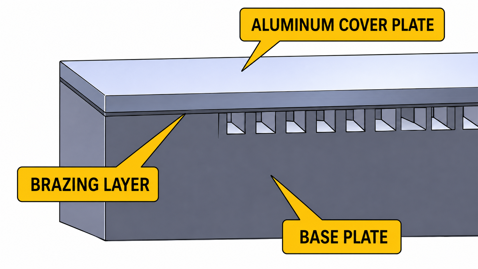
3. Performance Comparison: Verify the Part, Not a Marketing Percentage
3.1 Sealing and reliability
Both processes can deliver leak-tight cold plates. Vacuum-braze quality depends on surface cleanliness, joint clearance, filler placement, alloy compatibility, furnace vacuum and thermal uniformity. FSW quality depends on tool design, rotation and travel speed, plunge depth, root penetration, clamping and start/stop control.
A process name is not proof of sealing performance. The released drawing should define the test medium, test pressure, hold time, allowable pressure decay or leak rate, and acceptance after thermal or pressure cycling when the application requires it.
3.2 Joint strength and fatigue
FSW often provides a strong, dense joint because no cast weld pool is formed, but heat-affected and thermo-mechanically affected zones still exist. Vacuum-brazed joint strength depends on filler chemistry, clearance, bonded area and service temperature. Avoid specifying one universal percentage of parent-metal strength for either process.
3.3 Flatness and distortion
FSW limits heat to the weld region, which can reduce whole-part thermal distortion, especially on large plates. Mechanical downforce and an unbalanced path can still bend the plate or depress the cover. Vacuum brazing heats the complete assembly, so distortion is more sensitive to wall symmetry, material condition, fixture design, heating rate and cooling practice.
3.4 Channel cleanliness
FSW adds no filler inside the channel, so filler overflow cannot occur. Poor geometry or excessive plunge can still deform the cover toward the channel. Vacuum brazing requires tight control of filler quantity and joint gaps. Excess filler can enter narrow passages; insufficient filler can leave an incomplete bond.
4. Structural Freedom: Vacuum Brazing Reaches Hidden Interfaces; FSW Rewards Accessible Paths
· Vacuum brazing is well suited to stacked layers, internal fins, pin fields, complex chambers and assemblies that need many bonds in one cycle.
· FSW is well suited to machined-channel bases with a cover whose sealing path is accessible from the outside.
· FSW can follow straight, curved, circular and some three-dimensional paths. Feasibility depends on machine axes, turn radius, shoulder clearance, clamping and backing.
· Hybrid construction is possible. For example, internal elements may be brazed while an accessible service cover or port region uses another joining method after engineering validation.
5. Cost and Production: Compare Total Cost, Not the Price of One Weld
| Cost driver | Vacuum brazing | FSW |
| Pre-joining work | Filler preparation, precision cleaning, assembly and fixtures | Cover machining, joint preparation, rigid clamping and backing |
| Consumables | Filler or clad sheet; vacuum aluminum brazing is normally fluxless | No filler in the usual aluminum process; tools wear |
| Equipment | Vacuum furnace, loading fixtures and cycle control | High-stiffness FSW machine, spindle, force control and fixtures |
| Cycle model | Batch furnace cycle can join many interfaces | Automated path cycle; time grows with weld length |
| Post-process | Cleaning if required, flatness correction and machining | Flash or surface finishing, exit treatment and final machining |
| Quality cost | Include furnace-load risk, coupons and batch traceability | Include tool monitoring, path records and joint-start/end controls |
For a real comparison, include material yield, machining time, fixtures, batch loading, weld length, tool or filler consumption, leak-test time, rework limits, flatness correction and scrap risk. A lower joining quotation can still produce a higher finished-part cost.
6. Typical Failure Modes and Prevention
| Process | Typical risks | Design and process controls |
| Vacuum brazing | Incomplete wetting, insufficient filler, channel intrusion, local collapse, distortion or internal voids | Control alloy and temper, cleanliness, joint gap, filler volume, venting, fixture restraint, furnace uniformity and process coupons |
| FSW | Lack of root penetration, tunnel defects, hooking, thinning, exit keyhole or local distortion | Control tool geometry, plunge depth, rotation/travel speed, shoulder clearance, backing, clamping, path and exit strategy |
7. A Seven-Step Selection Workflow
1. Define the heat source, heat load, allowable temperature, coolant flow and pressure.
2. Confirm the base material, temper, wall thickness, joining area and flatness requirement.
3. Check whether the internal structure requires simultaneous bonding of fins, layers or many hidden interfaces.
4. Check whether an FSW tool can reach the full seal path with shoulder clearance and solid backing.
5. Compare the complete process chain for both options, including machining, fixtures, joining, inspection, finishing and scrap.
6. Define acceptance tests: CNC inspection, flatness, flow resistance, pressure proof, leakage, thermal performance and cycling as applicable.
7. Build representative samples, cut sections from the validation lot and freeze the qualified process before volume production.
8. Information to Send a Supplier Before Quotation
· 2D drawing and 3D model, including joint surfaces, channel layout, ports and keep-out zones.
· Material grade, temper, clad condition or filler requirement.
· Heat-source map, maximum heat load, allowable temperature rise and mounting interface.
· Coolant type, concentration, flow range, inlet temperature and pressure-drop limit.
· Working pressure, proof pressure, burst requirement and allowable leak rate.
· Flatness, surface roughness, thread, cleanliness and cosmetic requirements.
· Sample quantity, annual volume, target cost and required certifications or documentation.
9. Validation Plan: A Sample Is Only the First Step
| Validation item | Purpose | Common method |
| Dimensions and flatness | Confirm assembly and TIM contact | CMM, optical measurement, flatness fixture |
| Leak tightness | Verify the sealed circuit | Pressure decay, immersion, helium leak test |
| Proof and burst | Verify pressure margin | Hydrostatic or pneumatic method with a documented safety procedure |
| Flow resistance | Confirm hydraulic performance | Flow and differential-pressure test |
| Thermal performance | Confirm heat spreading and removal | Controlled heater map with inlet/outlet temperature measurement |
| Cycling and environment | Find fatigue or corrosion risks | Pressure cycling, thermal cycling, vibration or coolant compatibility as required |
| Internal quality | Support process development or failure analysis | Sectioning, microscopy, X-ray or CT when suitable |
10. Application Guidance
Evaluate vacuum brazing first when:
· The cold plate contains internal fins, turbulators, pin arrays or several bonded layers.
· Many internal interfaces must be joined in one controlled cycle.
· The product is compact, the heat flux is high, and the available external weld path is limited.
Evaluate FSW first when:
· The design is a machined aluminum base with an accessible cover-plate seam.
· The plate is large and flatness, mechanical joint strength and automated production are major priorities.
· The design can provide stable clamping, full backing and a controlled start/end area.
Conclusion: Lock the Process After Structure, Risk and Cost Are Reviewed Together
Vacuum brazing is often the practical answer for distributed internal joints and complex, multilayer thermal structures. FSW is often the practical answer for accessible aluminum cover joints where mechanical integrity, localized heat input and automation matter. Neither process removes the need for leak, pressure, thermal and life validation. The lowest-risk program selects the joining method early, designs the geometry around it and qualifies the complete manufacturing and inspection route.
| Need help selecting vacuum brazing or FSW for your cold plate?Send Cooling Thermal your 3D model, heat load, coolant, flow rate, pressure, flatness requirement and forecast volume. We can review thermal performance, manufacturability, prototype validation and production cost as one engineering package. |
FAQ
Which process provides better leak tightness?
Both can be leak-tight when design, parameters and inspection are controlled. Vacuum brazing depends heavily on cleanliness, joint gaps, filler control and furnace uniformity. FSW depends on tool design, parameters, root penetration, clamping and start/end control. The specified leak test decides whether the finished plate passes.
Does vacuum aluminum brazing require flux?
Normally no. Vacuum aluminum brazing is generally a fluxless process. The controlled vacuum environment and suitable alloy system support oxide disruption and filler wetting. Do not confuse it with controlled-atmosphere brazing, where flux may be used.
Is FSW limited to straight welds?
No. FSW can follow straight, curved, circular and some 3D paths. Cold-plate feasibility depends on machine motion, turn radius, tool-shoulder clearance, clamping and backing.
Which process causes less distortion?
FSW often reduces whole-part thermal distortion because heating is localized, but tool force and path balance still matter. Vacuum brazing heats the full assembly, so symmetry, temper, fixtures and the furnace cycle become critical. Both need a flatness-control plan.
Must every microchannel cold plate be vacuum brazed?
No. FSW may work when the channels are sealed by an accessible cover boundary with enough safe distance from the flow passages. Vacuum brazing is usually favored when internal fins or many distributed interfaces must be bonded.
Does an FSW cold plate need helium leak testing?
That depends on the allowable leak rate, coolant risk, working pressure and application. Data-center, medical, aerospace or electronics-adjacent systems often justify stricter micro-leak testing.
Which process is better for high-volume production?
Both can be scaled. FSW supports automated piece-by-piece production; vacuum brazing supports batch loading and simultaneous joining. Compare furnace utilization, weld length, fixtures, yield, inspection and post-processing to determine total cost.
-
Written by
CoolingThermal Engineering TeamCoolingThermal is an automation equipment manufacturer based in Kunshan, China, specializing in heat pipe and vapor chamber production equipment since 2017. Our engineering team designs, builds, and commissions complete production lines covering forming, degassing, welding, testing, and assembly processes. The technical content on this blog is written by the same team that develops the equipment — based on real production experience, not secondary research.


