

A vapor chamber lives or dies on one part most people never see: the wick. Get the wick wrong and the chamber dries out under load — the fluid can't get back to the hot spot fast enough, temperature spikes, and the part fails right when it's supposed to be working hardest. Five wick structures cover essentially all of current vapor chamber production — groove, sintered powder, sintered mesh, composite, and bionic. This guide covers what each one actually does, where the tradeoffs bite, and what each one costs you on the production floor, not just in a lab paper.
The core tradeoff: capillary force vs. permeability
Every wick design comes down to balancing two things that work against each other. Capillary force is what pulls condensed liquid back to the evaporator — the smaller the pore, the stronger the pull. Permeability is how easily that liquid can actually flow through the wick once it's moving — the smaller the pore, the more resistance it meets. Shrink the pore size and you get more pulling force but a harder path for the fluid to travel; open the pore up and the fluid moves more freely but with less force driving it home. Get this balance wrong in either direction and the wick can't keep up with the fluid demand at the evaporator — the chamber dries out, temperature spikes locally, and the part fails right where it's under the most load. Every wick type below is really just a different answer to this same tradeoff.
The 5 wick structures used in vapor chambers
Groove Wick
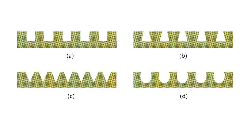
Grooves are machined or etched directly into the chamber wall, and capillary pressure builds as the liquid meniscus curves and shrinks inside the channel. This is the simplest wick to manufacture — cut with etching, laser machining, or stamping — and it gives comparatively high permeability, which is why it's been the workhorse choice for standard flat heat pipes and vapor chambers for decades. The catch is capillary force: it's limited by how narrow you can practically cut a groove, and pushing groove width down to raise capillary force runs into manufacturing cost fast. On its own, a groove wick struggles once heat flux climbs into high-power territory, which is why it's rarely used alone anymore on demanding designs — most current groove-based VCs pair it with a thin sintered layer on top to add capillary force without giving up the groove's flow path.
Sintered Powder Wick
Metal powder — almost always copper for VC work — is packed against the chamber wall and sintered at high temperature, fusing the particles into a porous matrix. This gives the strongest capillary force of any single-structure wick, because the pore network is fine and interconnected throughout. Published testing on powder-sintered VCs has measured thermal resistance in the range of roughly 0.04–0.24°C/W depending on heat load, powder size, and sintering thickness — powder diameter and how thick the sintered layer runs both move that number meaningfully. The tradeoff is exactly what the capillary-permeability relationship predicts: that same fine pore structure that gives it strong pulling force also gives it the highest flow resistance of the common wick types, and the internal pore structure that forms during sintering is harder to control precisely than a machined groove or a woven mesh — sinter parameters (temperature, atmosphere, hold time) all shift the final porosity, which is why sintering process control is as much a part of wick performance as the powder spec sheet.
Sintered Mesh Wick
Layers of fine metal mesh are sintered against the chamber wall, and capillary force comes from the gaps between the woven wires rather than a random powder pore network. Mesh wicks generally return liquid with less flow resistance than a powder wick of comparable capillary force, which is why mesh is often the choice when the goal is maximizing fluid return rather than maximizing pulling strength. Mesh count (commonly 50–300 mesh for VC work), wire diameter, and layer count are the main levers, and combining coarse and fine mesh layers is a common way to get more capillary force without giving up permeability. As with powder wicks, the contact between the mesh and the chamber wall creates its own thermal resistance, which is why diffusion bonding is often used here specifically to reduce that wall-to-wick contact resistance.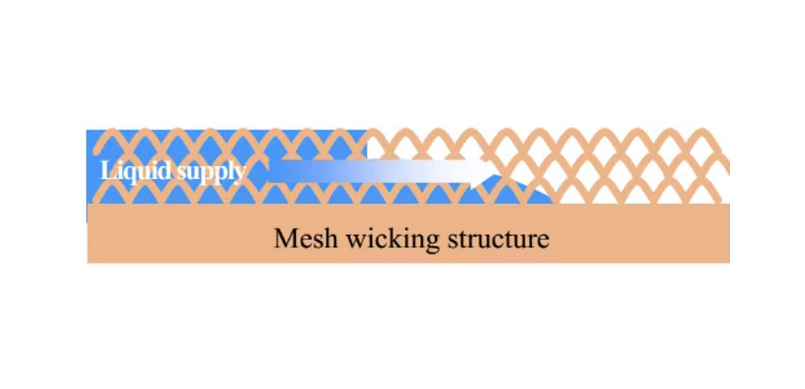
Composite Wick
A composite wick combines two of the structures above — groove plus sintered powder, or groove plus mesh, most commonly — so each layer covers the other's weak point. A typical arrangement sinters powder or mesh only in the high-heat-flux zone directly under the chip, while the surrounding area keeps a lower-resistance groove or mesh path for bulk fluid return. Published research on groove-powder composite designs has shown transfer capacity improvements of multiple times over a plain groove wick under the same conditions. The tradeoff is manufacturing complexity: a composite wick needs multiple process steps done in the right sequence and alignment, and mismatched interfaces between the two structure types can create their own flow resistance if the transition isn't designed carefully.Bionic (Biomimetic) Wick
Bionic wicks copy fluid-transport patterns found in nature — leaf vein branching, honeycomb cells, coral-like porous structures — on the idea that biological systems have already solved efficient fluid distribution under evolutionary pressure. Research designs using fractal, vein-like radial groove patterns have shown meaningfully lower thermal resistance and better temperature uniformity than uniform groove patterns in published testing, with some honeycomb-inspired designs reporting several times the transfer efficiency of a conventional array-groove wick under matched conditions. This is the newest category and the least standardized: these geometries are difficult to produce with conventional stamping or etching, and most bionic wick designs published so far have come out of additive manufacturing or advanced micro-etching processes rather than volume production lines. Worth watching, but not yet where most commercial VC production sits.
Wick structure comparison
| Wick Type | Capillary Force | Permeability | Manufacturing | Best Fit |
| Groove | Low–Moderate | High | Etch, laser, stamp — simplest, lowest cost | Standard/moderate heat flux |
| Sintered Powder | High | Low–Moderate | Powder fill + sinter — moderate complexity | High heat flux, compact designs |
| Sintered Mesh | Moderate–High | Moderate–High | Mesh layup + sinter/bond — moderate complexity | Balanced force and flow, thin VCs |
| Composite | Tunable by zone | Tunable by zone | Multi-step, precise alignment required | High-power, localized hot spots |
| Bionic | High (design-dependent) | High (design-dependent) | AM / advanced micro-etch — least standardized | R&D, next-gen ultra-thin/high-flux |
Which wick fits your application
There's no single best wick — the right one depends on your heat flux, thickness target, and what your production line can actually build repeatably. A few practical rules of thumb:
• Standard consumer electronics, moderate heat flux — groove or groove-plus-thin-mesh usually covers it at the lowest manufacturing cost.
• High-power, compact form factor (laptops, high-end GPUs) — sintered powder or sintered mesh, sized to the heat flux at the hot spot.
• High power with a concentrated hot spot (AI servers, high-TDP chips) — a composite wick that puts a stronger capillary structure only where the heat actually is.
• Ultra-thin form factors under 0.5mm — mesh or fine-groove composite, since thick sintered layers eat into the already-tight internal cavity.
• Cutting-edge R&D pushing heat flux limits — bionic and gradient designs are worth prototyping, but plan for a longer development cycle since these aren't turnkey production processes yet.
The manufacturing side most wick guides skip
A wick design that looks good on paper still has to survive contact with a real furnace. Sintering temperature, atmosphere, and hold time all shift the final pore structure of a powder or mesh wick, and running those parameters inconsistently is one of the most common reasons two VCs built to the same drawing end up with different thermal resistance. Where a wick relies on tight contact with the chamber wall — mesh wicks especially — diffusion bonding is what actually closes that wall-to-wick contact resistance rather than leaving it to chance. And for composite and bionic designs, the more process steps involved, the more each one needs to be controlled and verified — a wick that looks identical to the design intent under a microscope can still underperform if the sintering or bonding step wasn't dialed in.
If you want the full sequence from stamped plate to sealed, tested chamber, our vapor chamber manufacturing process guide covers where wick fabrication sits relative to sealing, degassing, and testing. For the heat-pipe-specific version of this same wick comparison — cylindrical geometry rather than flat — see our heat pipe wick structure guide.
Talk to us about your wick and process design
We build the sintering furnaces and diffusion bonding furnaces that turn a wick design into a repeatable part — sized and profiled to your powder, mesh, or composite structure, and validated on your own samples before shipment. If you're specifying a new wick design or troubleshooting inconsistent thermal resistance on an existing one, send us your drawings and target performance and we'll work through the process side with you.
FAQ
What is the best wick structure for a vapor chamber?
There isn't a single best one — it depends on heat flux, thickness, and manufacturing capability. Groove wicks suit standard, cost-sensitive designs; sintered powder or mesh suit higher heat flux; composite wicks suit high-power parts with a concentrated hot spot; bionic wicks are still mostly an R&D-stage option.
Why does a vapor chamber dry out?
Dry-out happens when the wick can't return liquid to the evaporator fast enough to keep up with how quickly it's being evaporated at the hot spot. This usually means the capillary force is too weak, the permeability is too low so the fluid can't flow fast enough even with adequate force, or the working fluid charge itself was set too low.
What is the difference between a sintered powder wick and a sintered mesh wick?
Both are formed by sintering metal against the chamber wall, but a powder wick's capillary structure comes from a randomly packed particle matrix, while a mesh wick's comes from the gaps in a woven wire pattern. Powder generally gives higher capillary force at the cost of more flow resistance; mesh generally gives easier fluid flow at somewhat lower capillary force.
What is a composite wick and why use one?
A composite wick combines two wick types in one chamber — commonly a groove or mesh structure for bulk fluid return, with sintered powder or mesh added only in the high-heat-flux zone under the chip. It lets a designer put strong capillary force exactly where it's needed without paying the flow-resistance cost of that structure across the whole chamber.
Does wick structure affect vapor chamber thickness?
Yes. Sintered powder and multi-layer mesh wicks add real thickness to the chamber wall, which matters on ultra-thin designs under roughly 0.5mm. Groove wicks and single-layer fine mesh generally allow a thinner overall chamber, which is one reason thin-and-light designs often lean toward mesh or fine-groove composite structures rather than a thick powder layer.
Can wick structure be customized for our specific chip and thermal profile?
Yes. Wick type, zone layout for composite designs, powder or mesh grade, and sintering or bonding parameters can all be matched to your chip's heat flux map and your target chamber thickness. We validate the wick and process on your own samples before committing to volume production.
-
Written by
CoolingThermal Engineering TeamCoolingThermal is an automation equipment manufacturer based in Kunshan, China, specializing in heat pipe and vapor chamber production equipment since 2017. Our engineering team designs, builds, and commissions complete production lines covering forming, degassing, welding, testing, and assembly processes. The technical content on this blog is written by the same team that develops the equipment — based on real production experience, not secondary research.


