

| Parameter Item | Specification/Value |
|---|---|
| Inspection Type | Surface / cosmetic defect inspection |
| Parts Inspected | Metal semi-finished thermal parts |
| Max Part Size | 130 × 130 mm |
| Throughput | Up to 500 pcs/h (UPH) |
| Cycle Time | About 6 s |
| Camera | 26 MP, 5120 × 5120, 14.7 fps |
| Lens | 35 mm fixed focal |
| Field of View | 80 × 80 mm |
| Optical Resolution | 0.0156 mm per pixel |
| Lighting | Four-zone combined bar light |
| Inspection Faces | Top, bottom, inner and outer sides |
| Imaging Stations | 3 |
| Material Handling | XYZR robot, vacuum nozzle, 4 pcs per pick |
| Loading / Unloading | 5-tray load / 3-tray unload, auto OK-NG sorting |
| Machine Size | 3500 × 1100 × 2100 mm |
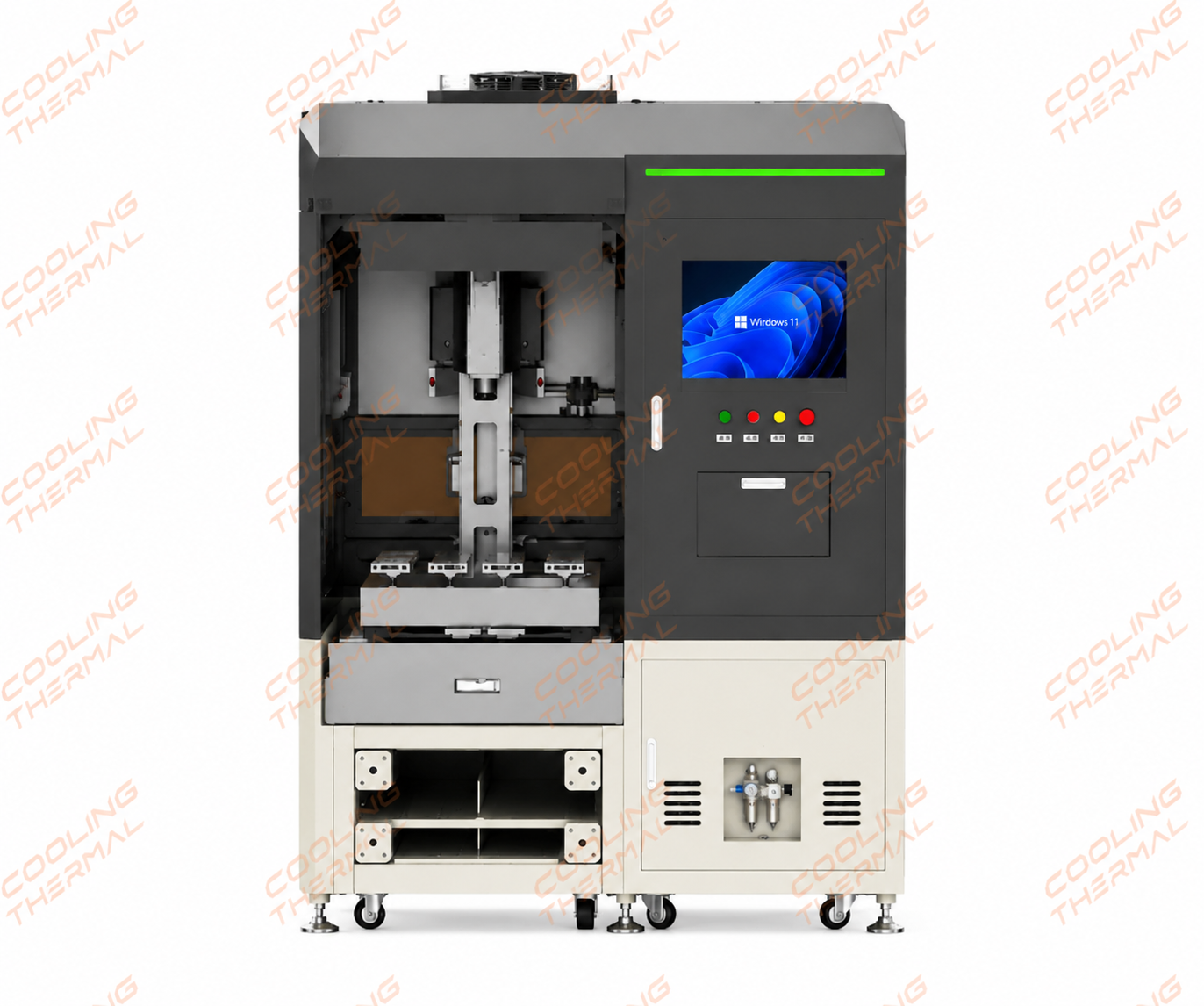
The system inspects parts up to 130 × 130 mm at up to 500 pieces per hour. Each imaging station uses a 26-megapixel camera at an optical resolution of about 0.0156 mm per pixel, so fine surface marks are resolved across the whole part. Multi-angle lighting reaches the top face, bottom face, and the inner and outer side faces, and a robotic arm moves parts between trays and stations with vacuum nozzles.
Each station takes several exposures under different light directions and combines them into normal, shape, and texture maps. This photometric method separates real surface defects from reflections and grain on textured metal, which is the main weakness of single-shot 2D inspection.
Advantages of the Automated Visual Inspection Machine
Photometric Multi-Angle Imaging
The machine lights each part from four directions and fuses the images into normal, shape, and texture maps. Dents, pits, and shallow pressure marks show up in the shape map even when they are almost invisible under flat lighting. That is what lets the system catch low-contrast defects on shiny and textured metal.
Low Missed-Defect Rate
Turntable-style first-generation inspection commonly leaves a missed-defect (escape) rate around 3% on metal parts, mostly from contamination and shallow marks the optics never imaged. The multi-angle imaging here lifts the imaging rate on exactly those defects and brings the escape rate down toward 0.05%.
Full-Surface Coverage in One Pass
Three imaging stations plus a repositioning camera cover the top, bottom, inner, and outer side faces. Every face of a part is checked in a single pass through the machine, so there is no separate manual side-face check afterward.
Automated Loading, Sorting, and Traceability
Parts feed in as stacked trays and the robot picks four at a time with vacuum nozzles. After inspection, good parts and rejects drop into separate trays automatically. The controller logs the result for each part, which gives the quality team defect counts and trends per batch.
How the Automated Visual Inspection Machine Works
Step 1 — Automated Loading
Operators place full trays on the infeed conveyor. A lift raises trays to the pick position, and the XYZR robot lifts parts with vacuum nozzles — the trays have no pick clearance, so nozzle handling is used instead of mechanical grippers. The robot moves four parts at a time to the first station.
Step 2 — Multi-Angle Imaging
At each station the part sits on a white background while the camera takes several exposures and the four-zone light changes direction. A hard camera trigger keeps the exposures tight so the station holds cycle time. The station builds normal, shape, and texture maps from those exposures.
Step 3 — Defect Detection
The software runs its defect models on the fused images while the mechanism moves the next part, so image processing overlaps with motion. It checks each face for dents, scratches, burrs, foreign material, contamination, discoloration, deformation, and marking or logo errors against the part rules.
Step 4 — OK / NG Sorting
After the last face is imaged, the robot places each part into the OK tray (or back onto the outfeed conveyor) or the NG tray based on the result. NG parts use a buffer position so the line does not stop for rejects, and empty trays are stacked and removed automatically.
Where the Visual Inspection Machine Fits in Your Production Line
Surface inspection sits at the back end of thermal component production, after forming and assembly and before packing. On a heat pipe or vapor chamber line it runs alongside functional checks such as leak testing and performance testing — those stations confirm the part works, while this station confirms the surface meets cosmetic spec.
The machine is built around each customer part. Part size, defect list, accept and reject limits, optics, and handling are set to your product before build. It can be supplied on its own or with the rest of a CoolingThermal testing and inspection line.


